

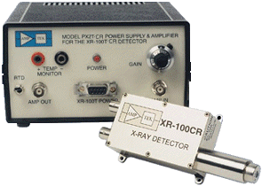
186 eV Resolution
All solid state design...
No more liquid nitrogen!
The XR-100CR represents a breakthrough in x-ray detector
technology by providing "off-the-shelf" performance
previously available only from expensive cryogenically cooled
systems.
Features
- Si-PIN Photodiode
- Thermoelectric Cooler
- Temperature Monitor
- Beryllium Window
- Hermetic Package (TO-8)
- Wide Detection Range
- Easy to Operate
Additional Information
|
Applications
|

|
Model XR-100CR is a new high performance x-ray
detector, preamplifier, and cooler
system using a thermoelectrically cooled Si-PIN photodiode as
an x-ray detector. Also mounted on the cooler are the input FET
and a novel feedback circuit. These components are kept at approximately
-30 °C, and can be monitored by an internal temperature sensor. The
hermetic TO-8 package of the detector has a light
tight, vacuum tight 1 mil (25 µm) Beryllium window to enable
soft x-ray detection.
Power to the XR-100CR is provided by the PX2CR Power Supply. The
PX2CR is AC powered and also includes a spectroscopy grade Shaping
Amplifier. The XR-100CR/PX2CR system ensures stable operation
in less than one minute from power turn-on.
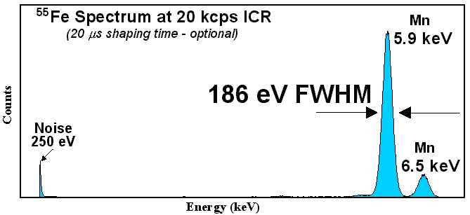
The resolution for the the 5.9 keV peak of 55Fe is 220 eV FWHM with 12µs shaping time constant
(standard) and 186 eV FWHM with 20µs shaping time (optional).
Theory of Operation
X rays interact with silicon atoms to create an average of one
electron/hole pair for every 3.62 eV of energy lost in the silicon.
Depending on the energy of the incoming radiation, this loss is
dominated by either the Photoelectric Effect or Compton scattering.
The probability or efficiency of the detector to "stop"
an X-Ray and create electron/hole pairs increases with the thickness
of the silicon. See Figures 2 and 3.
In order to facilitate the electron/hole collection process,
a 100 volt bias voltage is applied across the silicon.
This voltage is too high for operation at room temperature, as
it will cause excessive leakage, and eventually breakdown. Since
the detector in the XR-100CR is cooled, the leakage current is
reduced considerably, thus permitting the high bias voltage. This
higher voltage decreases the capacitance of the detector, which
lowers system noise.
Electron-hole pairs created by X-Rays which interact with the
silicon near the back contact of the detector are collected more
slowly than normal events. These events result in smaller than
normal charge collection and can increase the
background in an energy spectrum and produce false peaks. Such
events are characterized by slow risetime, and the PX2CR Amplifier
incorporates a Rise Time Discrimination circuit (RTD) which prevents
these pulses from being counted by the MCA. See figure 6. All spectra
shown in this specification were taken using RTD.
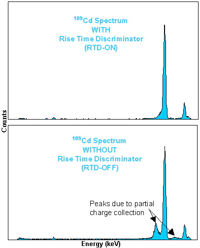
Figure 6. RTD vs. No RTD |
The thermoelectric cooler cools both the silicon detector and
the input FET transistor to the charge sensitive preamplifier.
Cooling the FET reduces its leakage current and increases the
transconductance, both of which reduce the electronic noise of
the system.
Since optical reset is not practical when the detector is a photodiode,
the XR-100CR incorporates a novel feedback method for the reset to the charge sensitive preamplifier.
The reset transistor, which is typically used in most other systems has been eliminated.
Instead, the reset is done through the high voltage connection to the detector by injecting
a precise charge pulse through the detector capacitance to the input FET.
This method eliminates the noise contribution of the reset transistor and further improves
the energy resolution of the system.
A temperature monitor chip is mounted on the cooled substrate
to provide a direct reading of the temperature of the internal
components, which will vary with room temperature. Below -20 °C,
the performance of the XR-100CR will not change with a temperature
variation of a few degrees. Hence, closed loop temperature control
is not necessary when using the XR-100CR at normal room temperature.
Vacuum Operation
The XR-100CR can be operated in air or in vacuum down to 10-8 Torr.
There are two ways the XR-100CR can be operated in vacuum: 1) The entire XR-100CR detector
and preamplifier box can be placed inside the chamber. In order to avoid overheating and
dissipate the 1 Watt of power needed to operate the XR-100CR, good heat conduction to the
chamber walls should be provided by using the four mounting holes. An optional Model
9DVF 9-Pin D vacuum feedthrough connector on a Conflat is available to connect the XR-100CR to the
PX2CR outside the vacuum chamber. 2) The XR-100CR can be located outside the vacuum chamber
to detect X-Rays inside the chamber through a standard Conflat compression O-ring port.
Optional Models EXV6 / EXV9 (6 or 9 inch) vacuum detector extenders are available for this
application. See photograph of XR-100CR with extender and Conflat and components for vacuum applications.
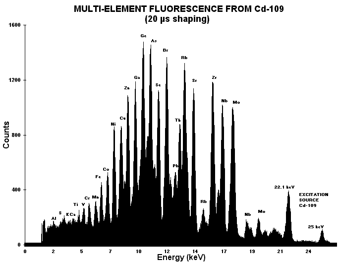
Figure 1. Sample Spectrum
| XR-100CR Specifications |
General |
| Detector Type | Si-PIN |
| Detector Size | 2.4 x 2.8 mm (7 mm2), standard |
| Silicon Thickness | 300 µm. See Figures 2 and 3 |
| Energy Resolution @ 5.9 keV (55Fe) | 220 eV FWHM with 12 µs shaping time (standard)
186 eV FWHM with 20 µs shaping time (optional)
280 eV FWHM with 6 µs shaping time(optional) |
| Background counts | <3 x 10⁻³/s, 2 keV to 150 keV |
| Detector Window | Be, 1 mil thick (25 µm) See Figures 2 and 3 |
| Charge Sensitive Preamplifier | Amptek custom design with reset through the H.V. connection |
| Case Size | 3.75 x 1.75 x 1.13 in (9.5 x 4.4 x 2.9 cm) |
| Weight | 4.4 ounces (125 g) |
| Total Power | <1 Watt |
Inputs |
| Test Input | 1 mV/keV, positive |
| Preamp Power | ±9 V @ 15 mA |
| Detector Power | +100 V @ 1 µA |
| Cooler Power | current = 0.7 A maximum, voltage = 2 V maximum |
Outputs |
| Preamplifier Sensitivity | 1 mV/keV |
| Preamplifier Polarity | Negative signal output (1 kohm maximum load) |
| Preamplifier Feedback | Reset through the detector capacitance |
| Temperature Monitor Sensitivity | 1 µA corresponds to 1 °K |
Options
- Other detector sizes (13 mm2 Si-PIN, 25mm2X500µm Si-PIN)
- Other Beryllium window thicknesses (0.3 mil - 7.5 µm) are available on special order.
- The XR-100CR (7mm2) can be special ordered with internal silver (Ag) or Tungsten (W) collimators.
- See also the XR100T-CZT specifications using Cadmium Zinc Telluride (CZT) detectors for high efficiency and high resolution Gamma Ray detection (1.5 keV FWHM @122 keV, 57Co).
- Collimator Kit for high flux applications.
Connectors
| Preamp Output | BNC coaxial connector |
| Test Input | BNC coaxial connector |
| Other connections | 6-Pin, LEMO connector with 5 ft cable |
6-Pin LEMO Connector
| Pin 1 | Temperature monitor |
| Pin 2 | +H.V. Detector Bias, +110 V maximum |
| Pin 3 | -9 V Preamp power |
| Pin 4 | +9 V Preamp power |
| Pin 5 | Cooler power return |
| Pin 6 | Cooler power (0 to +2.1 V @ 0.7 A maximum) |
| Case | Ground and shield |
Model PX2CR
Power Supply & Shaping Amplifier
General
Size: 6 x 6 x 3.5 in (15.3 x 15.3 x 8.9 cm)
Weight: 2.5 lbs (1.15 kg)
Input AC power to the PX2CR is provided through a standard
IEC 320 plug (110/250 VAC, 50-60 Hz). See Figure 5.
The four (4) DC Voltages needed to operate the XR100CR are supplied
through a female 9-Pin D-Connector on the PX2CR. The Pin list to this connector is given below.
The multiconductor cable which connects the PX2CR to the XR-100CR is provided with the system.
9-Pin D-Connector
| Pin 1 | +9 V Preamp power |
| Pin 2 | -9 V Preamp Power |
| Pin 3 | 0 to +3 V Cooler Power @ 0.7 A maximum |
| Pin 4 | +9 V Temperature Monitor Power |
| Pin 5 | +H.V. Detector Bias, +110 V maximum |
| Pin 6 | Ground and case |
| Pin 7 | Cooler power return |
| Pin 8 | Ground and case |
| Pin 9 | Ground and case |
PX2CR Shaping Amplifier Specifications
| Polarity | Positive unipolar |
| Shaping Time | 12 µs standard (6 and 20 µs optional) |
| Pulse Width | 22 µs. See Figure 4. |
| Shaping Type | 7 pole "Triangular" with base line
restoration, rise time discrimination (RTD), and pileup rejection. |
| Sensitivity | 0 to 1 V/keV (10 turn pot) |
| Gain | 0 to X1000 |
| Gain Shift | See figure 15 |
| Output Impedance | < 1 ohm |
The output pulse produced by the PX2CR Shaping Amplifier is optimum
for most applications using the Si-PIN photodiode detectors, and
can be connected directly to the input of a Multichannel Analyzer
(MCA). For optimum portability and versatility, use the Amptek MCA8000A "Pocket MCA"
with over 16k data channels.
Signal Connections
| Input from XR100CR | Front Panel BNC |
| Output to MCA | Front Panel BNC |
| Pileup Rejection (PU) | Rear Panel BNC, Positive TTL
For the duration of this output gate,
any detected pulse must be rejected by the MCA |
| Input Count Rate (ICR) | Rear Panel BNC, Positive TTL <2 µs
When connected to a counter
the ICR countrate corresponds to the total number of X-Ray events that strike the detector. |
This diagram shows the internal connections between the AXRCR hybrid
sensor and the electronics within the case, as well as the external
connections to the PX2CR.
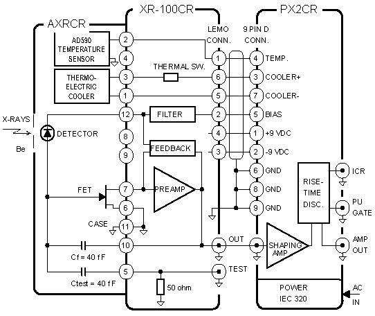
Figure 5. XR-100CR Connection Diagram
Figures and Additional Information
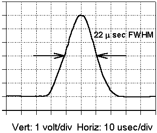
Figure 4. PX2CR Amplifier Output (12µs shaping time) |
| Shaping Time Constant | Pulse Width |
| Standard 12 µs | 22 µs FWHM |
| Optional 6 µs | 15 µs FWHM |
| Optional 20 µs | 54 µs FWHM |
|
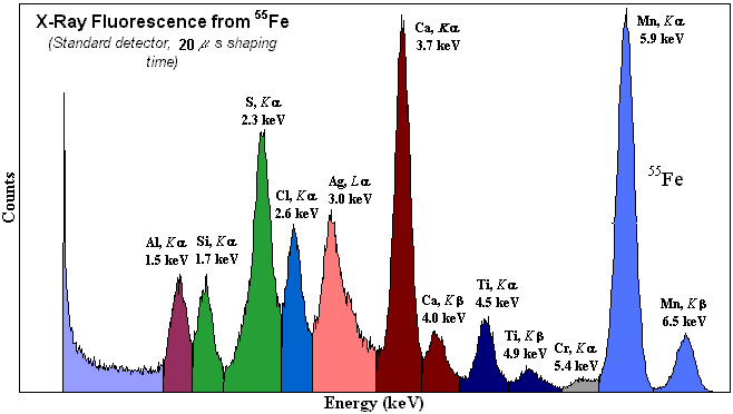
Figure 13. Sample Spectrum |
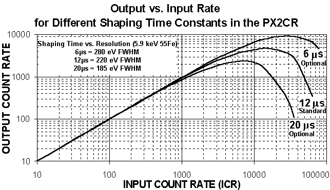
Figure 16. Output vs. Input Rate for different Shaping Time Constants |
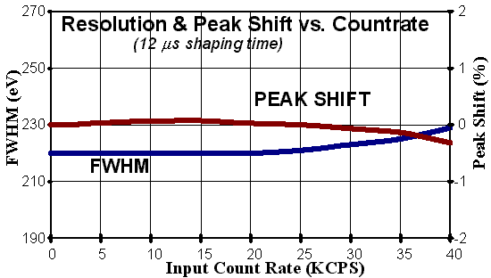
Figure 15. Resolution and Peak Shift vs. Count Rate
|
NOTE: The XR-100CR has replaced the XR-100T
See also the XR-100T-CZT Cadmium Zinc Telluride (CZT) detector for
high efficiency and high resolution Gamma Ray detection.
XR-100CR Specifications in PDF (382k)
All spectra taken with Amptek MCA8000A multichannel Analyzer.
Home Page | Products | Price list | Company Profile | Press Release
Revised February 9, 2001


