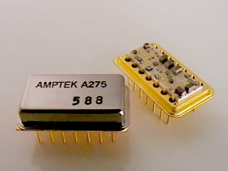

The A275 is a high performance hybrid differential op-amp developed as a pulse amplifier for spaceborne nuclear instrumentation.
Its low power dissipation (15 mW), high slew rate (100 V/µs), and low input noise (4 nV/Ö Hz), make it ideal for use in a wide range of op-amp applications. The A275 is packaged in a standard 14-pin hybrid DIP.
Figure 1. - Connection diagram.
| Pin Configuration | |
|---|---|
| Pin | Function |
| 1 | Inverting input |
| 2 | Non-inverting input |
| 3 | Bias adjust to Pin 4, (R > 3 kohm) |
| 4 | -Vs direct |
| 5 | -Vs through 50 ohms |
| 6 | Compensation to Pin 7, (C = 0 to 5 pF) |
| 7 | Case and Ground |
| 8 | Output through 50 ohms |
| 9 | Output direct |
| 10 | +Vs through 50 ohms |
| 11 | +Vs direct |
| 12,13,14 | Compensation (leave open for gain < 10, short for gain > 10) |
| Absolute Maximum Ratings | |
|---|---|
| Supply Voltage | ±8 V |
| Input Voltage | ±VS |
| Operating Temperature | -55 °C to +125 °C |
| Storage Temperature | -65 °C to +150 °C |
| Lead Temperature Range (Soldering, 10 sec.) | +300 °C |
| Electrical Characteristics VS = ? V, TA = +25 °C | ||||||
|---|---|---|---|---|---|---|
| Parameter | Symbol | Conditions | Min | Typ | Max | Units |
| Input Offset Voltage | VOS | 2 | 5 | mV | ||
| Input Offset Current | IOS | 0.1 | 0.6 | µA | ||
| Input Bias Current | IB | 1.5 | 4 | µA | ||
| Input Capacitance | CIN | 4 | pF | |||
| Differential Input Resistance | RIN | 44 | kohm | |||
| Common-Mode Input Resistance | RIN | 5 | 8 | Mohm | ||
| Common-Mode Rejection Ratio | CMRR | 90 | 95 | dB | ||
| Common-Mode Input Range | IVR | ?.5 | V | |||
| Power Supply Rejection Ratio | PSRR | 60 | dB | |||
| Large-Signal Voltage Gain @5kHz @5kHz @10MHz @10MHz |
ALFC ALF AHFC AHF |
compensated uncompensated compensated uncompensated |
64 72 16 24 |
66 74 20 28 |
dB | |
| Pulse Risetime (AV = 10) | trc tr | compensated uncompensated |
15 | 22 |
ns | |
| Output Voltage Swing | VOP VON | positive negative |
+4.5 | +4.7 |
-4.5 | V |
| Open Loop Output Resistance | RO | 750 | ohm | |||
| Output Short-Circuit Current | IOSC | source sink |
11 | mA | ||
| Slew Rate | SRP SRN | positive negative |
65 | 100 | V/µs | |
| Input Noise Voltage Density | eN | 4 | nV/ÖHz | |||
| Supply Current | IS | ±1.1 |
±1.25 |
±1.4 |
mA | |
| Power Consumption | PD | 15 | mW |
Figure 2. - A275 gain & phase
The A275 can be tested as a shaping amplifier by using the circuit shown below.
The PC-275 Test Board accommodates three (3) A275s and a BLR1 and produces a 5-pole pulse with 1 µs risetime (2.3 µs peaking time).
Dimensions: 3.5in X 1.75in (88.9mm X 44.45mm)
Figure 5. - General case for 3 and 5-pole response for different peaking times (TP)
Revised February 8, 2001