The BLR1 is a tranconductance amplifier with tranconductance of approximately 17ma/volt and very wide bandwidth. In operation, it amplifies both the DC baseline component and the pulse signal component by a large factor. Typically, with the PIN 12 output connected to a low impedance, the amplifier load is the internal 20 kohm resistor. The low frequency voltage gain at the amplifier output is 17ma/volt x 20 kohm = 340. The amplified pulses are clipped by the pair of Schottky diodes to an amplitude of +,- 0.5V and thus have little influence on the average output of the amplifier, which is dominated by the amplified baseline. This output is then passed through a low-pass RC flter formed by the first 10 kohm and the total capacitance (internal and external) from PIN 1 to ground. The filtered output is fed back to the input of the shaping amplifier chain to zero the baseline at the output of the amplifier chain.
Assume both BLR1 and the amplifier chain have zero offset voltage, so that in the absence of pulses the BLR1 output is zero, since no correction is required. Now assume 1 µs pulses are present at the output of the amplifier chain at a rate of 105/s. At the output of the BLR1 amplifier, this will produce a 10% duty cycle waveform with peak amplitude of 0.5 V. In order that the average of this signal be near zero volts, the baseline at this point will have to shift downward by (0.5V/9)=56mV. Dividing by the amplifier gain of 340, we get a baseline shift at the input of the BLR1 of just minus 160 µV.
                             0.5V (tWn)
            Baseline Shift = ------------------
                             AV (1-tWn)
where:Note that when the duty cycle reaches 50%, the baeline shift at the output of th BLR1 amplifier will reach -0.5V, at which point negative clipping will occur and the baseline can no longer be maintained. This can be considered to be BLR "saturation."
The above example is an ideal case. In a real case, there are several complicating factors which must be considered:
Since saturation is dependent on duty cycle, using a shorter peaking time, or pulse width, in the shaping amplifier will proportionally increase the saturation count rate. Too short of a peaking time however, will increase the overall noise of the system.
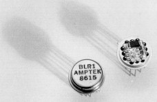
| Pin 1 | External capacitor to ground (as necessary to achieve stability) |
| Pin 4 | + Input |
| Pin 6 | - Input |
| Pin 7 | +6V (At 2.5 ma) |
| Pin 8 | -6V (At 2.5 ma) |
| Pin 9 | Case and ground |
| Pin 12 | Output (if the unit oscillates use PIN 1 for OUTPUT with and external 10 k replacing the internal 10 k.) |
| Pin 2,3,5,10,11 | No Connection |
Revised February 8, 2001