

![[a121 6k]](a121.jpg)
Model A121 is a hybrid charge sensitive preamplifier-discriminator
designed for use in fast pulse counting mode with microchannel plates,
channels electron multipliers, low gain photomultiplier tubes,
proportional counters and solid state detectors.
FEATURES:
- Sensitivity: 5 x 10⁴ electrons (Voltage Adjustable)
- Frequency: 12 MHz periodic
- Analog monitor output
- Output Pulse: 35 ns minimum (Adjustable)
- Vs = +4 to +7 VDC (20 mW)
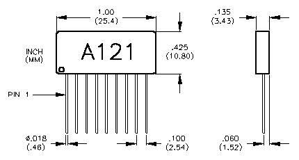
A121 DIMENSIONS
A121 RESPONSE
STEP INPUT THROUGH 2 pF TEST CAPACITOR
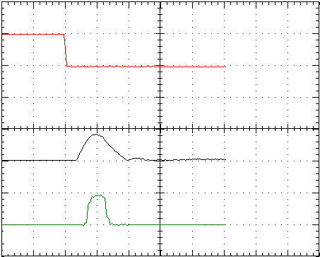
Top Trace: Input (Pin 1) 200mV/50ns
Middle Trace: Analog Out (Pin 5) 1V/50ns
Bottom Trace: Ouput (Pin 9) 5V/50ns
AT THRESHOLD:
| Input Test | 4 mV through 2 pF |
| Q = CV = 0.008 pC = 5 x 10⁴ electrons |
| Analog Output (Pin 5) Sensitivity | 140 mV (15V/pC) |
| Analog Output Risetime | 10 ns |
| Output (Pin 9) | 5 V; 50 ns wide |
A121 PIN CONFIGURATION
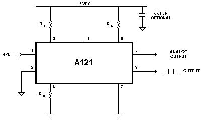
| Pin 1 | Input |
| Pin 2 | Ground and Case |
| Pin 3 | Threshold Adjust (5k ohms < RT: open for maximum sensitivity), see Figure B |
| Pin 4 | Vs (+5 to +7 VDC MAX.)
|
| Pin 5 | Analog Monitor |
| Pin 6 | Pulse Width Adjustment (RH <30k ohms)
RH = 0 For Minimum Pulse Width of 35 ns, see Figure C |
| Pin 7 | Ground and Case |
| Pin 8 | Deadtime Adjustment (RL <30k ohms)
RL = 0 For Minimum Dead Time of 80 ns, see Figure A |
| Pin 9 | Output |
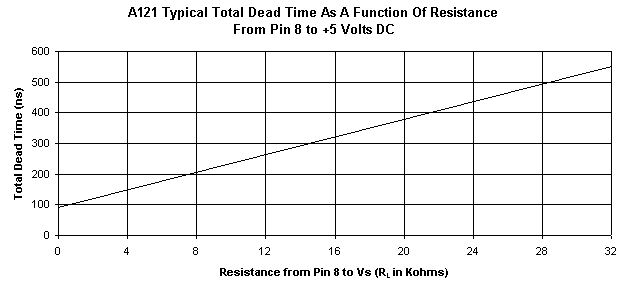
Figure A
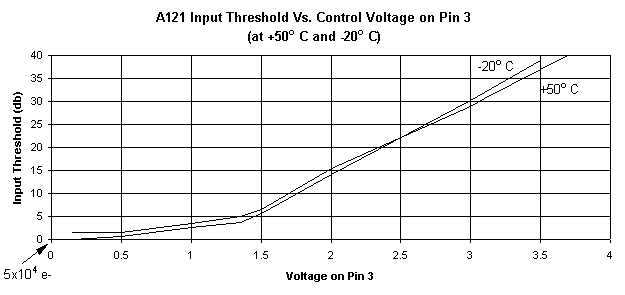
Figure B
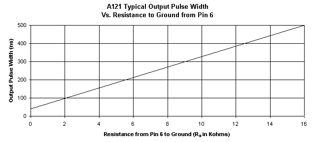
Figure C
PC121 Test board for the A121
![[pc121 layout]](pc121_a.gif)
DIMENSION: 1.75 in X 1.75 in (4.5 cm X 4.5 cm)
MATERIAL: FR4
![[pc121 schematic]](pc121_b.gif)
PC121 OPERATING NOTES
- The PC121 accommodates two of the A121s, side by side.
- The input (Pin 1) of the A121 is held at a DC level of 1.2 Volts. Capacitors C1 and C2 isolate the input of the A121 from accidentally grounding it. Both C1 and C2 are rated at 200 Volts. THEY ARE NOT HIGH VOLTAGE COUPLING CAPACITORS. If the detector signal is at high voltage, an external high voltage coupling capacitor of adequate voltage rating must be connected from the detector to C1 and/or C2. This high voltage capacitor is not supplied with the PC121 due to the large variations of detector types and applications. Since the A121 is used in similar applications to the A111, please refer to the A111 connection diagrams and applications for additional information.
- Due to the high sensitivity at the input and the fast rise time signals that are generated at the output of the A121, care must be taken to the connections of the external wiring in order to avoid oscillations and noise pick-up. Enclosing the PC121 inside a small metal box is recommended.
NOTES ON A121
- PIN 1, INPUT
Pin 1 has a DC level of 1.2 volts. This DC level should not be changed by
external circuitry. Pin 1 should be AC coupled to the detector.
The High Voltage coupling capacitor should have adequate voltage rating
in order to prevent breakdown which could harm the A121.
- Protection to the A121 can be provided as follows:

- PIN 3, THRESHOLD ADJUST
Threshold to the A121 can be changed remotely by changing the voltage level
on Pin 3. A resistor from Pin 3 to Vs can be added in order to raise the threshold
on the A121. The impedance at Pin 3 is about 10k ohms. (see Figure B)
- PIN 5, ANALOG MONITOR
Pin 5 provides a positive analog pulse output from the preamplifier section just
prior to the discriminator with a rise time of about 10 ns. At maximum sensitivity
(Pin 3 = 0 volts) the amplitude of this pulse is proportional to the input charge, A = 15 V/pC.
At threshold this will correspond to a 120 mV pulse. If a voltage is present on Pin3,
the size of the analog pulse will be divided by the same threshold attenuation factor
the voltage produced.Example: If 1.3 volts is present on Pin 3 (6dB attenuation is a factor of 2),
the size of the analog pulse will be 60 mV/pC. This output must be capacitively coupled
to external circuitry and can be used to monitor detector gain variations by performing
pulse height analysis.
- PIN 9, OUTPUT
The final output stage of the A121 is produced from a 74AC00 gate with a 200 ohm series resistor.
Hybrid Selection Guide | Home Page |
Products | Pricelist | Company Profile | Press Release
Revised February 8, 2001
![[a121 6k]](a121.jpg)

![[a121 6k]](a121.jpg)


![[pc121 layout]](pc121_a.gif)
![[pc121 schematic]](pc121_b.gif)
