Designed for direct applications in the field of aerospace instrumentation, mass spectrometers, laboratory and research experiments, medical electronics, and electro-optical systems.
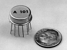
Model A101 is a hybrid charge sensitive preamplifier, discriminator, and pulse shaper developed especially for instrumentation employing photomultiplier tubes, channel electron multipliers and other low capacitance charge producing detectors in the pulse counting mode. While this unit was specifically designed for satellite instrumentation, the following unique characteristics make it equally useful for space, laboratory and commercial applications:
| Vs = +5 V, T = +25 °C | |
|---|---|
| Threshold | Model A101 has a nominal threshold referred to the input of 1.6 x 10 coulomb. This is equivalent to 10 electrons. The threshold can be increased by the addition of a resistor between Pin 9 and 12. See Figure 1. |
| Stability | < 1.5% of threshold, 0 to +50 ºC. See Figure 3. |
| Noise | RMS noise level < 0.4% of threshold. |
| Protection | Back-to-back diodes to ground. |
| Detector Capacitance | 0 to 60 pF |
1) Pin 5 provides a positive 5 volts output pulse capable of interfacing directly with CMOS.
| Risetime | 6 ns |
| Falltime | 20 ns |
| Width | 220 ns nominal. May be increased to greater than 1 µs by the addition of a capacitor between Pin 3 and 4. See Fig. 2. |
| Amplitude | 5 volts |
2) Pin 6 is an open collector output and with an external pullup resistor provides a negative going pulse (the complement of Pin 5). This output can drive TTL and can be wireor'ed with other units. Pullup resistor may be connected to Vs or to other positive supply up to +15 V.
| Count Rate | 4 x 10 CPS, Periodic |
| Pulse Pair Resolution | 250 ns |
| Operating Voltage | +4 to +10 VDC |
| Operating Current | 3 mA quiescent, 4 mA @ 10 CPS |
| Temperature | -55 to +70 ºC operational |
| Warranty | One year |
| Raditation Resistance | > 10 rad(Si) |
| Package | 12-Pin, TO-8 case. |
| Screening | Amptek High Reliability |
| Test Board | PC-11 |
The case is internally connected to Pin 1, ground.
Figure 1.
The A101 can be tested with a pulser by using a small 2pF test capacitor to inject a test charge into the input. The unit will trigger on the negative-going edge of the pulse which should have a much longer fall time (> 1 µs) or a square wave may be used. (If a square wave is used, triggering on the positive-going edge will occur for large pulses.)
Charge transfer in the test circuit is according to Q = C·V where Q = total amount charge, C = capacitance, and V = voltage. Use only a small capacitor in this circuit (1 to 10 pF). DO NOT connect a low impedance pulser through 500 pF when testing as this will produce a large pulse through the input transistor and may cause irreversible damage.
Tr < 20 ns, Tf > 1 µs
Negative going
Amplitude: 0.25 V = 0.5 picocoulomb
Pin 6 is an open collector output and should be left unconnected if not used. A negative going output can be obtained by connecting a pullup resistor (typically 1 kohm) between Vs and Pin 6. The pullup resistor may be tied to any positive voltage up to 15 V (as required for example, in interfacing with particular logic families.) In multi-detector systems, where more than one preamp drives the same counter, the open collector outputs of several A101s can be connected together to the counter input with a single pullup resistor. DO NOT CONNECT THIS PIN DIRECTLY TO Vs (PIN 2) AS THIS MAY DAMAGE OUTPUT STAGE AND VOID WARRANTY.
The output pulse with can be increased by the connection of a capacitor between Pin 3 and 4. See Figure 2 for typical values.
Figure 2.
If the standard pulse width is adequate Pin 3 and 4 must be left unconnected.
Figure 3.
Use care in soldering leads - avoid overheating.
| Pin 1 | Ground |
| Pin 2 | Vs (+4 to +10 VDC) |
| Pin 3 | Pulse Width Adjust |
| Pin 4 | Pulse Width Adjust |
| Pin 5 | Positive Output |
| Pin 6 | Open Collector Output |
| Pin 8 | No Connection |
| Pin 8 | No Connection |
| Pin 9 | Threshold Adjust |
| Pin 10 | No Connection |
| Pin 11 | No Connection |
| Pin 12 | Input |
![[pc-11 layout]](pc11b.gif)
Dimensions: 1.75 in X 1.75 in (4.45cm X 4.45cm)
| Inputs | |
| IN | Detector Input; Pin 12; should be AC coupled with a high voltage capacitor (500-1000pF) |
| DET | Provides post to connect the detector and input capacitor |
| TEST IN | Input to test circuit as described in specifications |
| Vs | Pin 2; supply voltage (+4 to +10 VDC) |
| H.V. | Provides post to connect the detector to the high voltage supply through a resistor |
| Outputs | |
| +OUT | Positive, TTL type output from Pin 5 |
| O.C. OUT | Negative; open collector output from Pin 6 (must be connected through 1 kohm to Vs) |
| BUF OUT | Positive output through a Buffer/Line Driver IC from Pin 5 |
| Components | |
| Cv | Filter capacitor (1uF) |
| Rp | Pullup resistor (1 kohm) |
| C | Test capacitor (2 pF) |
| R | Test pulse termination resistor (50 ohm) |
| Rt | Threshold adjust resistor |
| Cw | Pulse width adjustment capacitor |
| Cd | High voltage detector coupling capacitor (user supplied) |
| Rb | Detector Bias resistor (user supplied) |
| U2 | Line driver TPS2829 |
![[pc-11 schematic]](pc11.gif)
Revised February 8, 2001