The MD-501 AMPTEKTRON® contains:
- Channel Electron Multiplier (CEM)
- High Voltage Supply
- Charge Sensitive Preamplifier & Discriminator
- Line Driver
- Fully Packaged Electronics
![[block diagram]](md501_2.gif)
Figure 1. - Functional diagram

The MD-501 AMPTEKTRON® contains:
|
![[block diagram]](md501_2.gif) Figure 1. - Functional diagram |
The AMPTEKTRON® is a compact, easy to use electron multiplier system capable of detecting Electrons, Ions, VUV, Soft X-rays, and other Nuclear Particles at rates greater than one million events per second. It is configured in a pulse counting mode and operates from a single low voltage supply.
The AMPTEKTRON® is designed for direct applications in the field of mass spectrometer, laboratory and research experiments, vacuum process monitoring and beam diagnosis.
Features
|
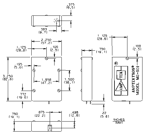
![[product drawing]](md501_3.gif) Figure 2. - External view |
The Amptektron® should be operated in pressures less than 1 x 10E-4 torr. Prior to shipment the Amptektron is "burnt-in" for 28 hours of continuous operation resulting in 2 x 10E9 total accumulated counts. The final pressure after "burn-in" is typically 4 x 10E-8 torr. The MD-501 is intended for high vacuum operations down to pressures of 1 x 10E-8 torr. The unit is not bakable above 100 ºC and thus not appropriate for some Ultra High Vacuum (UHV) systems with pressures of 1 x 10E-9 torr and lower. For UHV use see the MD-502 which is bakeable to 300 ºC and contains only UHV compatable materials.
The following figure shows schematically the process that occurs inside the Amptektron to detect energetic particles or photons. The primary incoming radiation passes through the Amptektron inlet aperture and strikes the surface of the channel electron multiplier. If the energy of the collision is sufficient, at least one electron is ejected from the CEM wall. The ejected electrons are accelerated into the interior of the CEM by the local electric field developed by the bias voltage. If the magnitude of the bias voltage is sufficient, the accelerated electrons acquire enough energy to trigger more secondaries when they strike the CEM surface again. This process continues down the length of the CEM, striking the CEM surface many times, each time generating more and more secondaries. A single photon or particle input event will trigger an output electron avalanche of more than 1 x 10E7 electrons!
![[CEM drawing]](md501_4.gif)
Figure 3. - Channel Electron Multiplier (CEM)
The Amptektron® is intended to operate from a range of low voltage supplies (+10 to +15 VDC). To allow this range of operation there is a series voltage regulator that supplies a stable +5 VDC to the charge amplifier/discriminator (A101A) and the output driver.
The Amptektron® current requirements vary somewhat as a function of the supply voltage. The following figure gives a typical power consumption for low counting rates.
![[current vs. voltage plot]](md501_5.gif)
Figure 4. - Nominal Amptektron power consumption
Mechanical mounting may use any or all of the six #4-40 screws that retain the printed circuit card and aperture assembly. The aperture plate block may be removed and drilled or tapped for custom attachment. The aperture plate has been nickel plated and the surface will be difficult to drill until the plating surface has been penetrated.
A CEM responds to a variety of stimuli in various degrees. The absolute efficiency of a given CEM to a specified input will depend on the surface cleanliness of the CEM, any pre-acceleration potentials that may exist, and the energy/mass characteristics of the input. There have been many CEM efficiency estimates published in scientific literature, not all in consistent agreement. Following are some typical curves that have been extracted from that literature. They should provide an order of magnitude estimate of the sensitivity of an Amptektron.
The MD-501 circuitry places a bias voltage on the CEM input funnel to provide an acceleration potential to incoming low energy particles. For ions the funnel is set to -400 volts and for electrons it is set to +100 volts. A jumper on the printed circuit card is used to select the mode. Note that this pre-acceleration potential provides rejection for low energy particles of the opposite polarity.
![[efficiency vs. energy plot]](md501_6.gif)
Figure 5. - CEM Electron Response
From: Pashman, G., et al., Rev. of Sci. Inst., 41, 1706 (1970)
![[efficiency vs. energy plot]](md501_7.gif)
Figure 6. - CEM Proton Efficiency
From: Egidi, Rev. of Sci. Inst., 40, 88 (1969)
![[efficiency vs. wavelength plot]](md501_8.gif)
Figure 7. - CEM absolute vacuum ultraviolet response
From: Johnson, M.C., Rev. of Sci. Inst., 40, 311 (1969)
![[efficiency vs. wavelength plot]](md501_9.gif)
Figure 8. - CEM x-ray response
From: Smith, D.G., et al., Trans. of the IEEE, NS-15, 541 (1968)
![[configuration drawing]](md501_10.gif)
![[configuration drawing]](md501_11.gif)
Figure 10. - Retarding potential analyzer
![[configuration drawing]](md501_12.gif)
Figure 11. - Curved plate analyzer
![[configuration drawing]](md501_13.gif)
Figure 12. - Vacuum process monitoring

Revised February 7, 2001