|
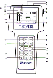
1. |
Lemo quick-disconnect connectors. |
|
2. |
Serial RS 232 port. |
|
3. |
Digital thickness reading. |
|
4. |
Built-in auto-probe zero block. |
|
5. |
Measurement bar. |
|
6. |
Right edge calibration. |
|
7. |
GRID allows access to grid functions (creating,deleting or selecting a grid use). |
|
8. |
CLEAR Key deletes reading and/or waveform from memory location. |
|
9. |
CAL Key calibrates material velocity. |
|
10. |
ENTER Key stores reading to internal data logger. |
|
11. |
Right and left arrow key functions vary depending on mode of operation. |
|
12. |
GATE Key sets two adjustable gates. |
|
13. |
Power Key. |
|
14. |
SET UP determines operating mode, units of measure and other options. |
|
15. |
DISP Key calibrates left and right sides of A-Scan display. |
|
16. |
SCAN Key enables rapid scanning of material and minimum thickness capture. |
|
17. |
PROBE selects probe type. |
|
18. |
WAVE freezes waveform images on display and enables waveform storage. |
|
19. |
Left edge calibration. |
|
20.
21.
22.
23.
24.
25. |
A-Scan waveform display.
Grid location.
Low battery indicator.
Units of measure.
Coupling indicator.
Memory status. |


